|
|
|
|
|
|
|
|
|
|
|
|
|
|
|
|
|
|
|
|
|
|
|
|
|
|
|
|
|
|
|
|
|
|
|
 |
| |
>
INTRODUCTION
a
fascination with imagination |
| |
>
THEME PARK MAGIC
inspirational rides and attractions |
| |
>
A PHANTOM PLOT UNFOLDS
a 2003 test from Disneyland ideas |
| |
>
THE HAUNTING BEGINS
five
years of Halloween, 2004-2008 |
|
>
BACK FROM THE GRAVE
2010-2011 with new technology |
| |
>
A 2013 RESURRECTION
a mix of new and age-old effects |
| |
>
DAWN OF THE UNDEAD
2014
show, part one |
| |
>
THE ZOMBIES EMERGE
2014 show, part two |
| |
>
A CHANGING CONCEPT
2015 show, part one |
| |
>
BUILDING PNEUMATIC FIGURES
2015 show, part two |
| |
>
ROLL UP, ROLL UP!
2015
show, part three |
| |
>
INTO THE TUNNEL...
2016
show, part one |
| |
>
MAKING MONSTERS MOVE
2016
show, part two |
| |
>
TO HELL AND BACK
2016 show, part three |
| |
>
SHARPENING THE
SENSES
2017 show, part one |
| |
>
A MAGNETIC ATTRACTION
2017 show, part two |
| |
>
THE BIG EXECUTION
2017 show, part three |
|
|
|
| |
A name to conjure with... |
|
|
|
|
|
|
|
|
|
|
|
|
|
|
|
|
|
|
|
|
|
|
|
|
|
|
|
|
|
|
|
|
|
|
|
|
|
| |
I decided that
the walkthrough would be called the ‘Tunnel of Hell’, owing
to the series of ghoulish scenes I had developed showing
various figures in tortuous situations, and demon-like
monsters that would suddenly move towards visitors. I
visualised a big imposing entrance, like an archway, with
the name as a large sign directly above where people walked
in.
|
|
|
| |
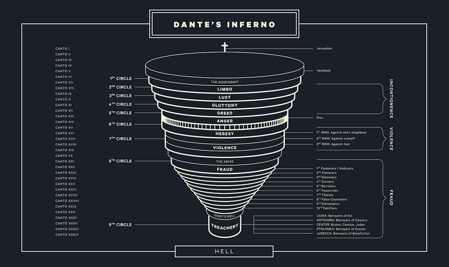
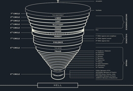
A lot of the
inspiration for this came from reading parts of Dante’s
Inferno, one of the three parts of his 14th century work
The Divine Comedy. Dante conceives Hell as an
enormous pit made up of nine circles, containing trapped
souls guilty of sins such as gluttony, fraud, treachery…each
one darker than the last. He journeys down through each
circle and witnesses horrific torments inflicted on these
souls.
All this was very powerful and scary imagery, and it gave me
a lot of ideas. Some of them made it into the final tunnel
design. |
|
 |
|
|
| |
|
Image credit: Daniel Brokstad
danielbrokstad.com |
|
|
|
|
|
|
|
|
|
|
|
|
|
|
|
|
|
|
|
|
|
|
|
|
|
|
|
|
|
|
|
|
|
|
|
| |
 |
See my first layout plans and
descriptions of effects
with this set of early concept ideas
(pdf,
2.0mb) |
|
|
|
|
|
|
|
|
|
|
|
|
|
|
|
| |
|
|
|
|
|
|
|
|
|
|
|
|
|
|
|
|
|
|
|
|
|
|
|
|
|
|
|
|
|
|
|
|
| |
Triggering the scares... |
|
|
|
|
|
|
|
|
|
|
|
|
|
|
|
|
|
|
|
|
|
|
|
|
|
|
|
|
|
|
|
|
|
|
|
|
|
|
|
|
|
|
|
|
|
|
|
|
|
|
|
|
|
| |
 |
|
I wanted the
tunnel to have the feel of a ghost train at a funfair, in
the sense that as you went through it, things happened to
YOU! Visitors wandering through the dimly lit passageways
would encounter a number of shock effects, triggered as they
got near to each window. I wanted it to make people jump!
But how to
trigger these effects? Since 2006, I’d used PIR sensors to
detect motion in the garden, and these would then trigger
whatever effect was on the end of them. PIRs could pick up
motion in a wide area, which was particularly useful when
detecting people first entering the garden. But in the
tunnel, there were clearly defined points where I wanted the
effects to happen. The answer was to use infra-red barriers.
|
|
|
|
|
|
|
|
|
|
|
|
|
|
|
|
|
|
|
|
|
|
|
|
|
|
|
|
|
|
|
|
|
|
|
|
|
|
|
|
|
|
|
|
 |
|
|
|
|
|
|
|
|
|
|
|
|
|
 |
|
|
| |
|
|
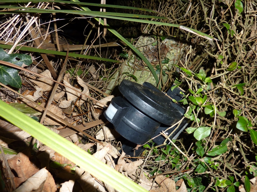
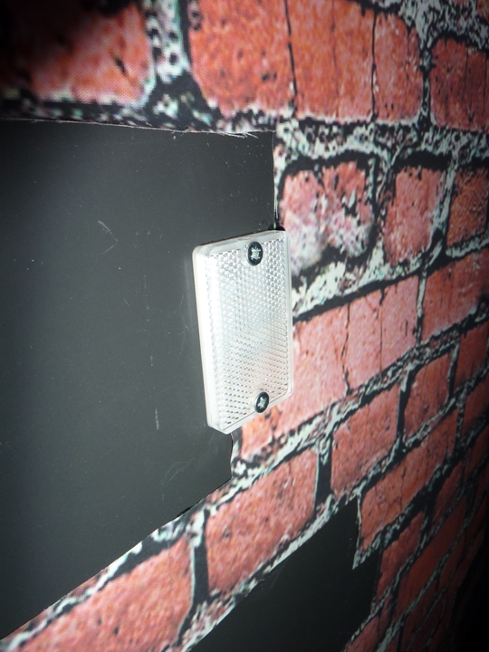
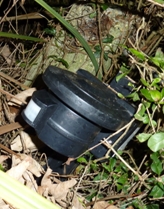
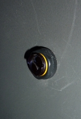
< Set into the
walls at the required points in the tunnel were four of
these devices – small cylinders about 20mm in diameter.
These emitted an invisible infra-red beam.
> On the wall directly opposite, a small reflective plate
was fixed. Under normal conditions, the infra-red light
would be reflected back at the sensor. As soon as someone
walked through the beam, the light would stop being
reflected and the sensor would trigger. This worked very
reliably. |
|
|
|
| |
|
|
|
|
|
|
|
|
|
|
|
|
|
|
|
|
|
|
|
|
|
|
|
|
|
|
|
|
|
|
|
|
|
|
|
|
|
| |
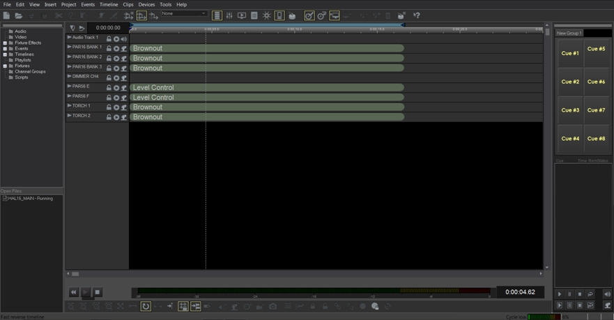
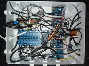
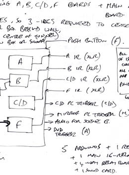
This year, the
system in charge of controlling everything was set up in a
shed situated over a wall behind the tunnel. In here was the
airbrush compressor (from 2015) for connection to the
pneumatics, shelves of amplifiers for all the sounds (the
whole setup used ten speakers!) and the main control box.
|
|
| |
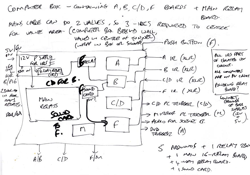
Inside this box
were four Arduino Uno microcontroller boards, each
controlling a scene. There were also two Adafruit Audio FX
boards, containing sounds for two of the scenes. Each of the
Arduino boards controlled relays on a 16-way relay board.
This was where everything to be switched (12V air valves,
mains relays for lights, trigger pins for sounds etc.) was
assigned a relay.
When I was developing this system, I gave each of the six
scenes a letter, so they were simply known as A, B, C, D, E
and F, with A being the first scene and F the final scene.
The C and D scenes would be two figures opposite each other
that were part of the same animation sequence, so they were
known as 'C/D' and shared the same controller. Scene E did
not require a controller as it was to be animated using
motors that would run continuously, instead of being a
momentary, triggered effect.
|
|
 |
|
|
|
|
|
|
|
|
|
|
|
|
|
|
|
|
|
|
|
|
|
|
|
|
|
|
|
|
|
|
|
|
|
|
|
|
|
|
|
| |
 |
|
|
The order of the
scenes going through the tunnel was to be this:
SCENE A (IR triggered)
- swarm of wasps stinging man
(motorised figure with projection and sound)
SCENE B (IR triggered)
- wailing prisoner in chains
(pneumatic figure with sound and light)
SCENE C/D (IR triggered)
– trolls wielding rocks
(two pneumatic figures with sound and light)
SCENE E
- floating souls and reaper
(non-triggering scene with sound)
SCENE F (IR triggered)
– devil with fire
(pneumatic figure with sound) |
|
|
 |
|
| |
|
|
|
|
|
|
|
|
|
|
|
|
|
|
|
|
|
|
|
|
|
|
|
|
|
|
|
|
|
|
|
|
|
|
|
|
|
| |
There was also
to be another separate effect in the porch, just outside the
tunnel exit (known as M, the mirror scene). As it was to
feature another pneumatic figure, it also needed an Arduino
controller. To hold this, a separate control box with a
4-way relay board was installed inside the house, which
connected to the main box outside.
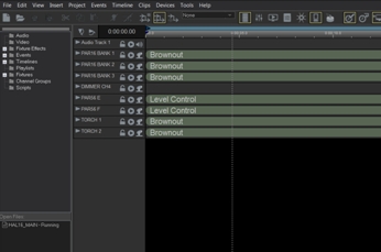
There were also three computers, each running DMX timelines
on
VenueMagic SC+. Two of
these were used to control lighting and sound for scenes
(C/D and M). The C/D computer was triggered from the outside
control box by the relevant Arduino board. The third
computer ran a looped sequence to control the dimmers which
powered all the flickering PAR 16s inside the tunnel, as
well as the two torches either side of the entrance, and
other LED PAR 56s used for scene lighting. It also ran the
main soundtrack music of the tunnel on a seamless loop.
|
|
 |
|
|
|
|
|
|
|
|
|
|
|
|
|
|
|
|
|
|
|
|
|
|
|
|
|
|
|
|
|
|
|
|
|
|
|
|
|
|
|
|
|
|
|
|
|
|
|
|
|
|
|
|
|
|
|
|
|
|
| |
Adding the
pneumatics |
|
|
|
|
|
|
|
|
|
|
|
|
|
|
|
|
|
|
|
|
|
|
|
|
|
|
|
|
|
|
|
|
|
|
|
|
|
|
|
|
| |
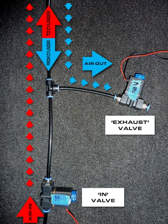
The moving
figures in scenes B, C/D, F and M were fitted with
100mm-stroke pneumatic cylinders, replacing the air muscles
I used in 2015. These cylinders connected via a network of
6mm air pipe to a box located in the closed-off space in the
centre of the tunnel. This box contained a number of 12V
4-way air valves that were responsible for allowing air from
the compressor into and out of the cylinders. These were
switched on and off by the relevant Arduino Uno boards and
relays in the control box in the shed. |
|
| |
 |
|
|
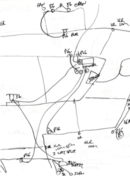
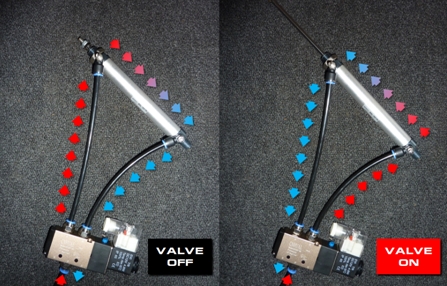
Surely I
should have used 4-way valves?
Good question! There’s a bit of a story here…The cylinders
were of the double-acting type, which means that air can
be forced in from either end depending on which direction
the cylinder needs to move (ie. out-stroke or in-stroke) –
the exact job of a 4-way valve.
Originally, I did connect the cylinders to this type of
valve, as in the diagram to the left. Their configuration
allowed air into the cylinders such that they remained fixed
at one extreme (eg. piston rod fully in-stroked). Then, when
the valve was turned on, it ‘flip-flopped’ over so that the
air now flowed in through the other end of the cylinder, and
it moved to its opposite state (piston rod fully
out-stroked). When the valve was de-powered, the direction
was reversed again and the rod returned inwards. |
|
|
|
|
|
|
|
|
|
|
|
|
|
|
|
|
|
|
|
|
|
|
|
|
|
|
|
|
|
|
|
|
|
|
|
|
|
|
|
| |
|
See me doing an early test of a figure
frame with a 4-way valve and pneumatic
cylinder
(.mp4,
4.0mb) |
|
|
|
|
|
|
|
|
|
|
|
|
|
|
|
|
|
|
|
|
|
|
|
|
|
|
|
|
|
|
|
|
|
|
|
|
|
|
|
|
|
| |
This all seemed
to work during testing...but when it came to fitting the
whole system of five valves together during the installation
week, I just couldn’t get them air-tight enough for the
compressor to maintain the required air pressure! I
definitely had the correct type of fittings in the valves,
they were of the right thread and they were super tight, but
collectively they still leaked enough that the compressor
could never reach its 4-bar target, and as a result, would
never switch off! It would have overheated if it ran
continuously, so some urgent re-thinking was required.
|
|
| |
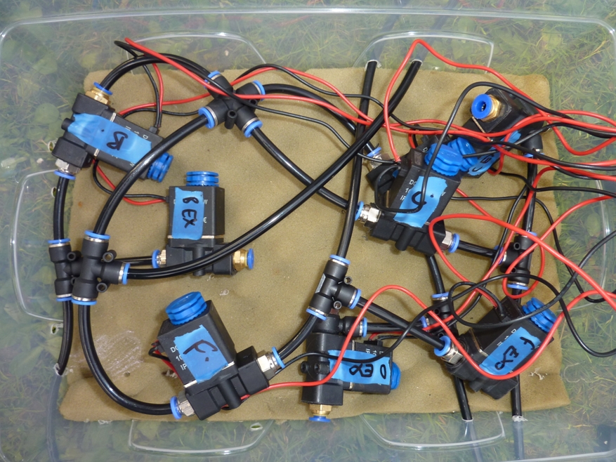
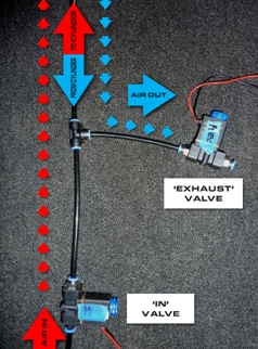
The solution
(from bits I had available) was to use two standard 12V
1-way air valves per cylinder, and operate them as
single-acting, similar to how the air muscles in the 2015
display worked. I called the valves for each cylinder IN and
EXHAUST. They were connected with a T-piece, as shown in the
picture to the right. (click it to enlarge)
The idea was that each cylinder would have a resting state
(piston rod fully in-stroked), and the moving part of each
figure was attached to a fixed point with strong elastic
cord. When the first valve (IN) was turned on, with the
EXHAUST valve closed, air would enter the cylinder and the
piston rod would out-stroke. Then the IN valve was closed
again, and when it was time for the figure to move back, the
EXHAUST valve was opened. The air would escape from the
cylinder, and the elastic cord would return the piston rod
and figure back to its starting position.
This may not have been the system I expected to create (!)
but it did have the advantage of needing less air pipe
overall! Now only one piece of pipe needed to run between
the valves and the cylinder, rather than two. I was also
able to finally achieve a very air-tight system, capable of
supporting the necessary air pressure. (The figures all
operated using around 3-bar pressure).
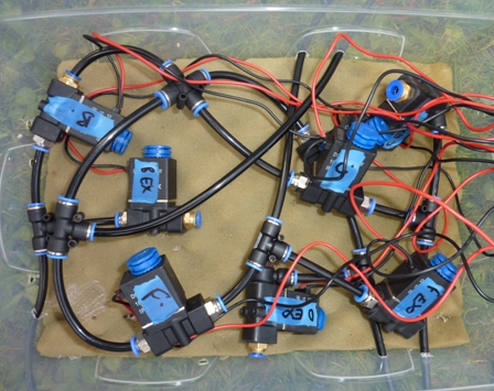
There were five pneumatic effects in the display (one each
in scenes B, C, D, F and M). Eight valves were installed in
a box (for scenes B, C, D and F) and the two valves for the
M scene in the porch were positioned directly behind the
wall for this scene. These two valves were controlled by the
Arduino board and relays inside the house.
|
|
|
 |
|
|
|
|
|
|
|
|
|
|
|
|
|
|
|
|
|
|
|
|
|
|
|
|
|
|
|
|
|
|
|
|
|
|
|
|
|
|
|
| |
 |
|
The eight valves
in the central box were surrounded with acoustic foam in an
attempt to dampen their noise a bit – the switching and
releasing of air was quite loud! But once they were in place
behind the tunnel walls, you could hardly hear them and they
did a great job throughout the whole week leading up to the
big night with never a problem.
As I had a total of five pneumatic figures this year, I
programmed each scene controller to wait for a period of
about 10 seconds after each figure had done its thing,
before being able to be triggered again. There was the very
likely possibility of multiple figures being triggered at
the same time, and so a higher air demand would be put on
the compressor. With this delay in place, the compressor
would have a bit more of a chance to restore the air
pressure level before more triggering took place. As another
precaution, I designed all the figures in such a way that
even if they didn’t move at all due to low air pressure,
their resting positions were such that even with just their
accompanying lights and sound active, they still looked
effective. As it turned out, I needn't have worried - the
compressor did a fine job, firing on all five cylinders...! |
|
|
|
|
|
|
|
|
|
|
|
|
|
|
|
|
|
|
|
|
|
|
|
|
|
|
|
|
|
|
|
|
|
|
|
|
|
|
|
| |
Building the
figures...and recycling old ones! |
|
|
|
|
|
|
|
|
|
|
|
|
|
|
|
|
|
|
|
|
|
|
|
|
|
|
|
|
|
|
|
|
|
|
|
|
|
|
|
|
|
| |
 |
|
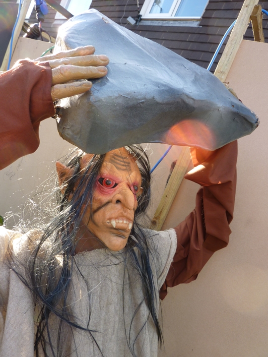
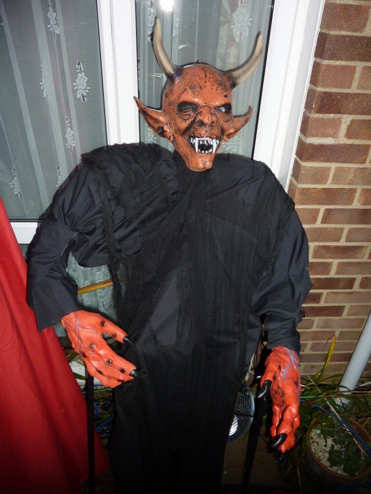
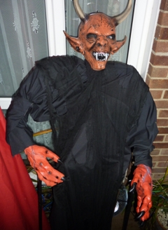
The plastic pipe
frames of the 2015 figures were modified to create the new
ones. The wolfman became the devil (scene F, right), as he
was already floor-standing, and just needed his legs
straightening! The fortune teller frame was given legs and
became the man being stung by wasps (scene A), and the
grotesque frame was used for the mirror scene (M).
Frames for the
static figures of 2015 were modified to have hinged pieces
that attached to the cylinders. These were used for the C/D
troll figures (left), and a new frame was made for the scene
B figure.
The figures were built up using polystyrene heads with latex
masks attached (including one from an Irish company called
Rubber Johnnies...
hmm). The arms and legs were ‘bulked up’ using foam lagging,
then covered in different materials, such as hessian, gauze
and muslin.
|
|
|
|
 |
|
|
|
|
|
|
|
|
|
|
|
|
|
|
|
|
|
|
|
|
|
|
|
|
|
|
|
|
|
|
|
|
|
|
|
|
|
|
|
| |
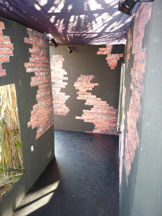
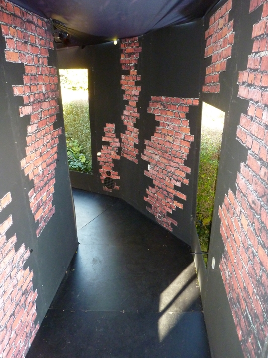
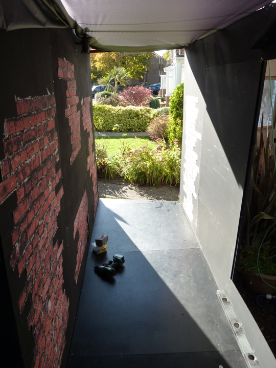
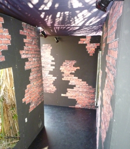
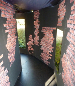
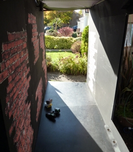
Here are some
pictures of the tunnel interior before the scenes were added
in. |
|
|
|
|
|
|
|
|
|
|
|
|
|
|
|
|
|
|
|
|
|
|
|
|
|
|
|
|
|
|
|
|
|
|
|
|
|
|
|
|
|
| |
 |
|
|
 |
|
|
 |
|
|
|
|
|
|
|
|
|
|
|
|
|
|
|
|
|
|
|
|
|
|
|
|
|
|
|
|
|
|
|
|
|
|
|
|
|
|
|
| |
Apart from my
little urgent pneumatics reworking, the rest of the tunnel
had gone together a treat! By Sunday 30th October, the only
things left to install was some extra lighting in the porch,
and the signs to go outside the entrance of the tunnel. The
whole interior of the tunnel was fully working and tested,
and so it meant that for the first time ever, we could all
have a little preview of the show ourselves that evening, a
day early!
The next day came, the finishing touches were completed, and
in the evening, it was time for the tunnel to open!...
|
|
|
|
|
|
|
|
|
|
|
|
|
|
|
|
|
|
|
|
|
|
|
|
|
|
|
|
|
|
|
|
|
|
|
|
|
|
|
|
| |
 |
|
|
|
|
|
|
|
|
|
|
|
|
|
|
|
|
|
|
|
|
|
|
|
|
|
|
|
|
|
|
|
 |
|
|
|
|
|
|
|
|
|
|
|
|
|
|
|
|
|
|
|
|
|
|
|
|
|
|
|
|
|
|
|
|
|
|
|
|
|
|
|
|
|