|
|
|
|
|
|
|
|
|
|
|
|
|
|
|
|
|
|
|
|
|
|
|
|
|
|
|
|
 |
| |
>
INTRODUCTION
a
fascination with imagination |
| |
>
THEME PARK MAGIC
inspirational rides and attractions |
| |
>
A PHANTOM PLOT UNFOLDS
a 2003 test from Disneyland ideas |
| |
>
THE HAUNTING BEGINS
five
years of Halloween, 2004-2008 |
|
>
BACK FROM THE GRAVE
2010-2011 with new technology |
| |
>
A 2013 RESURRECTION
a mix of new and age-old effects |
| |
>
DAWN OF THE UNDEAD
2014
show, part one |
| |
>
THE ZOMBIES EMERGE
2014 show, part two |
| |
>
A CHANGING CONCEPT
2015 show, part one |
| |
>
BUILDING PNEUMATIC FIGURES
2015 show, part two |
| |
>
ROLL UP, ROLL UP!
2015
show, part three |
| |
>
INTO THE TUNNEL...
2016
show, part one |
| |
>
MAKING MONSTERS MOVE
2016
show, part two |
| |
>
TO HELL AND BACK
2016 show, part three |
| |
>
SHARPENING THE SENSES
2017 show, part one |
| |
>
A MAGNETIC ATTRACTION
2017 show, part two |
| |
>
THE BIG EXECUTION
2017 show, part three |
|
|
|
| |
Animation and decapitation |
|
|
|
|
|
|
|
|
|
|
|
|
|
|
|
|
|
|
|
|
|
|
|
|
|
|
|
|
| |
|
This year, there
was a lot to animate! All these props and figures that I’d
come up with… I wanted them all to move! There was lots of
variation in these required movements too; linear motion,
rotary motion, dropping and winching… but how best to do
each one?
While Disney's latest series of Audio-Animatronics have been
designated A-100, mine might be classified as
A-0.1! But what my figures might have lacked in realism
and life-like human movement, I hoped they would make up for
in old-fashioned ghost train clunkiness and charm!
I think even figures animated in a very basic way have the
power to startle and shock when combined with the right
sound and lighting. Both are useful tools that can emphasise
and highlight, to help create a more impressive overall
effect, as well as mask and disguise, in order to misdirect
the observer's attention.
The list below describes the scenes that I had come up with for
the dungeon. All of them were to be sensor-activated, and
incorporate movement.
|
|
| |
|
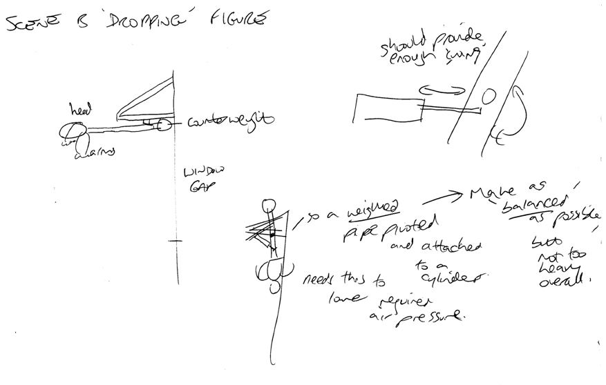
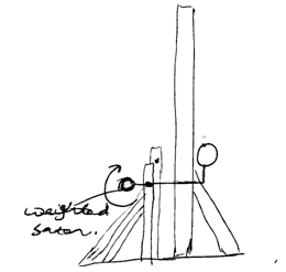
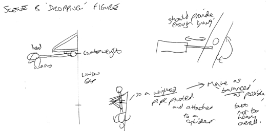
SCENE A (IR triggered)
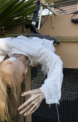
- axeman, transformation into headless figure
(one-way mirror effect with two pneumatic figures, sound and
lighting cues)
SCENE B (IR triggered)
- hanging figure falling downwards
(pneumatic figure with sound and lighting cues)
SCENE C/D (IR triggered)
– figure holding rope, guillotine with victim
(pneumatic figure, motorised prop with moving victim figure,
sound and lighting cues)
SCENE E (IR triggered)
- figure on torture rack, standing figure operating it
(motorised figure with moving handle, static figure, sound
cues)
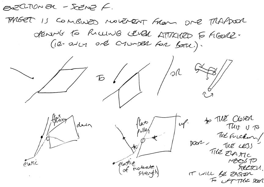
SCENE F (IR triggered)
– figure on gallows, falling through trapdoors
(motorised figure on rope, static figure, pneumatic doors,
smoke, sound and lighting cues)
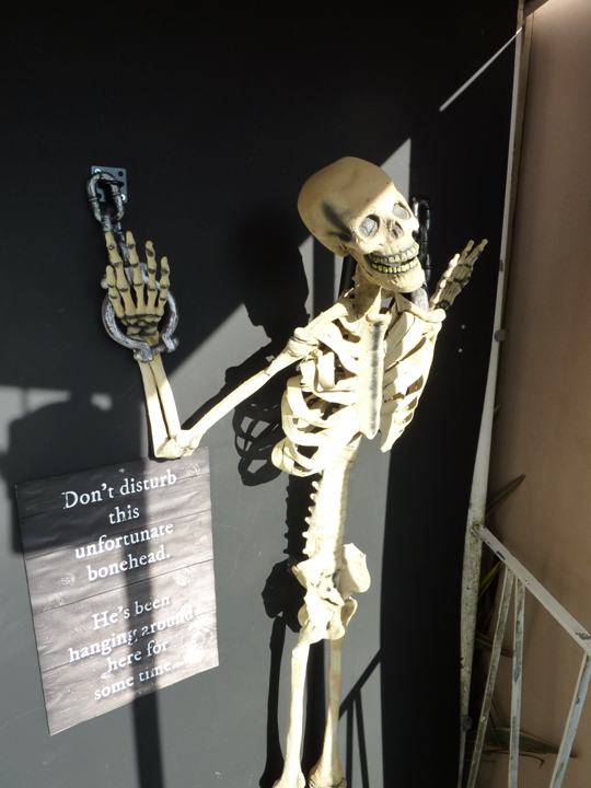
SCENE S (IR triggered) (in porch)
– skeleton hanging on wall, jumps forward at guests
(pneumatic figure with sound cue)
SCENE X (IR coin detection trigger) (at exit)
– ratcatcher figure, moves when coin dropped into donation
slot (motorised figure, sound cues) |
|
 |
|
|
|
|
|
|
|
|
|
|
|
|
|
|
|
|
|
|
|
| |
|
|
 |
|
|
|
|
|
|
|
|
|
|
|
|
|
|
|
|
|
|
|
|
|
|
|
|
|
|
|
| |
|
Most of the
standing figures were to be moved by pneumatic cylinders,
much like in the previous year’s show; tilting towards
visitors as they approached, then backwards again to a
resting position. I liked using a pneumatic method for these
as this could be used to create movement that was quite fast
and fierce!
For this reason I chose also to use a cylinder on each of
the trapdoors in the gallows scene at the end of the
walkthrough (scene F). This would allow them to quickly fall open, allowing
the man in the noose above to fall through, and then close
again once this figure was winched clear of them.
|
|
|
|
| |
|
 |
|
|
I planned to use
the same reliable but relatively small airbrush compressor
as in the previous two shows to drive these cylinders. There
were to be seven in total, and this was probably a sensible
limit, given that more than one effect was likely to be
triggered at a time.
However, there was a trick that I used to increase the
number of animated objects without needing extra cylinders –
the idea of ‘linked’ movement. In other words; don’t
separately animate a figure, attach it to an already moving
part!
This trick was
useful for moving the lever held by the 'executioner' figure
on the gallows as the trapdoors opened (linking the lever to
the nearest door with wire), moving the hands of the
torturer (fixing them to the rotating handle of the torture
rack) and also with the falling blade of the guillotine - it
could push the head of its victim downwards too as it fell. |
|
|
|
| |
|
|
|
|
|
|
|
|
|
|
|
|
|
|
|
|
|
|
|
|
|
|
|
|
|
|
|
|
|
|
| |
|
This worked by means of mounting the head on a weighted
'see-saw' type arm. Ordinarily the head was slightly less
heavy than the weight, so it was held upright in position.
When the blade came down and hit the arm, the combined
weight was now heavier, so it tilted downwards. As soon as
the blade was lifted clear again, the head was restored
upwards. No motor or air cylinder required!
It would have been great to have had a much larger
compressor offering all the air in the world, but I needed
something that wasn't going to rattle the neighbours'
windows, so I had to stick with my trusty little airbrush
model with its modest 3-litre air tank!
As a result, it was all about finding a balance between making sure that
enough things moved for as many visitors as possible (rather than
them walking through and finding every scene inactive or
resetting) and programming enough 'rest' time for each
effect (only a few seconds) so that the compressor would not
be heavily drained in the likely event of multiple people walking the
circuit at the same time. |
|
|
|
 |
|
|
|
|
|
|
|
|
|
|
|
|
|
|
|
|
|
|
|
|
|
|
|
|
|
|
|
|
|
|
|
|
|
| |
|
 |
|
|
|
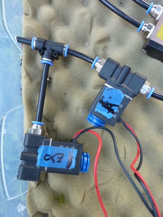
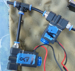
I used a mix of
air valves this year.
The previous air-leaking problem I had with those pesky
5-port, 4-way valves was solved this year by generous winds of PTFE tape
around each fitting on their inlets!
However, my emergency fix of using two single way valves
per figure had actually produced perfectly acceptable
movement, and this method also only required ‘half’ the air
demand, since elastic was used to restore each piston to its
resting position, and not another cylinder-sized quantity of
air to push it back. |
|
|
|
 |
|
|
|
|
|
|
|
|
|
|
|
|
|
|
|
|
|
|
|
|
|
|
|
|
|
|
|
|
|
|
|
|
|
| |
|
For this reason,
I decided that all three standing figures that were to be animated, and the
two trapdoors in the final scene, would use the same single-valve
arrangement as the previous year. Three 4-way valves were
also used, notably on the hanging figure in scene B, which I
wanted to drop down suddenly into view and startle visitors! |
|
|
|
|
|
|
|
|
|
|
|
|
|
|
|
|
|
|
|
|
|
|
|
|
|
|
|
|
|
|
|
|
|
| |
|
 |
|
|
|
|
|
|
 |
|
|
| |
|
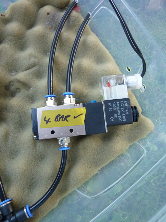
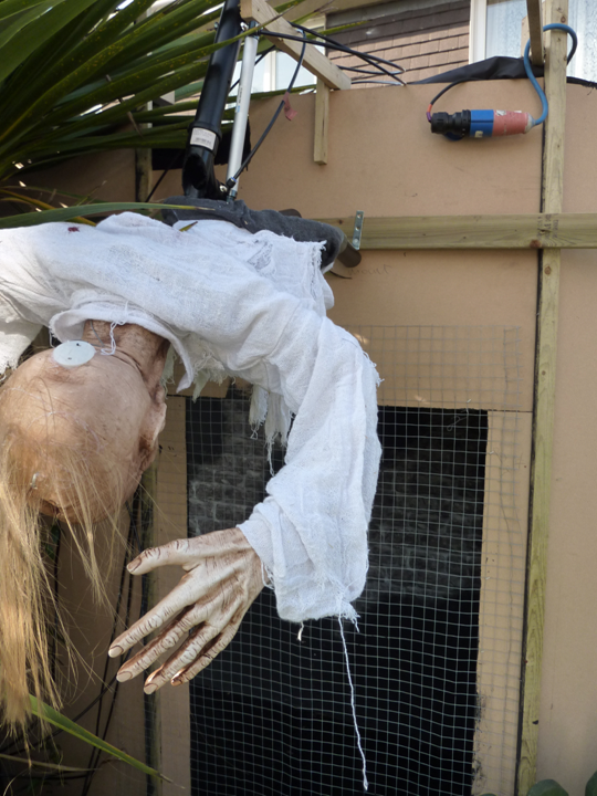
For this
movement, it was important that there was sufficient air
pressure to lift the figure, mounted on a hinged arm,
upwards and out of sight. But also I wanted it to fall
downwards and crash into the mesh on the window in quite a
violent way when triggered. With a 1-way valve
simply ‘releasing’ the air pressure, the figure fell slowly
and gently under its own weight – not very scary...
So instead, I fitted a 4-way valve, to provide air pressure
that moved the cylinder quickly in both directions; the
figure no longer fell, it was forced downwards with some
speed! |
|
|
|
|
|
|
|
| |
|
|
|
|
|
|
|
|
|
|
|
|
|
|
|
|
|
|
|
|
|
|
|
|
|
|
|
|
|
|
| |
|
Rotary motion |
|
|
|
|
|
|
|
|
|
|
|
|
|
|
|
|
|
|
|
|
|
|
|
|
|
|
|
|
|
|
|
|
|
| |
|
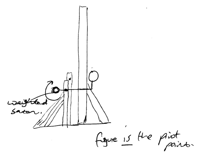
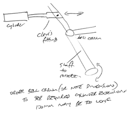
There was
another type of motion to be created too… I wanted the
axeman at the entrance to repeatedly tap the blade of the
big axe he was holding against his other hand, in eager
anticipation of his victims! This movement would use another
air cylinder, but this time, it would need to produce rotary
motion; pivoting the axe up and down by about 45 degrees. |
|
|
|
|
|
|
|
|
|
|
|
|
|
|
|
|
|
|
|
|
|
|
|
|
|
|
|
|
|
|
|
|
|
| |
|
 |
|
|
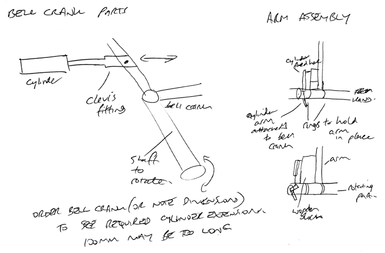
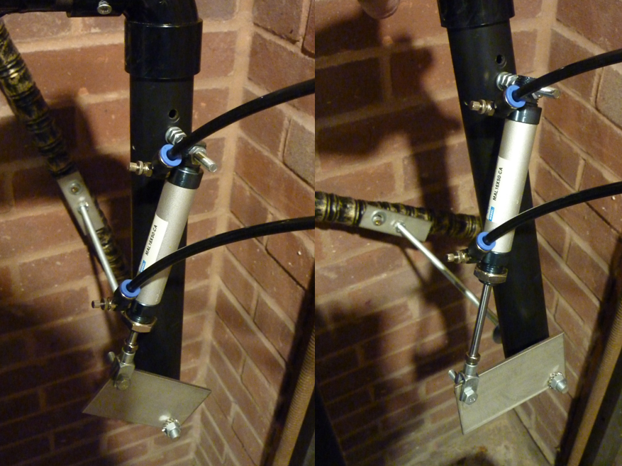
I hadn’t tried
creating this movement with a figure before, so for a few
hints, I got in contact with my number one pneumatics
advisor…David
Buckley!
His suggestion was to use an arrangement called a bellcrank, to convert the linear ‘push-pull’ motion from the
cylinder into the rotation needed to move the axe.
The shaft of the axe was threaded onto a long metal rod.
Fixed at the other end of the rod was a metal plate, about
5cm long, extending perpendicularly from it.
|
|
|
 |
|
|
|
|
|
|
|
|
|
|
|
|
|
|
|
|
|
|
|
|
|
|
|
|
|
|
|
|
|
|
|
|
|
| |
|
A 50mm air cylinder was then attached via a clevis fitting to the
opposite end of this metal plate. As the cylinder piston
pushed and pulled, it caused the plate to be moved around
the fulcrum created by the rod; the rod rotated.
The cylinder for this was driven by another 4-way valve,
since I wanted the axe to be lifted and lowered in a
controlled way. Again, this provided movement at the same
speed in both directions.
|
|
|
| |
|
|
|
|
|
|
|
|
|
|
|
|
|
|
|
|
|
|
|
|
|
|
|
|
|
|
|
|
|
|
| |
|
Motors and magnets |
|
|
|
|
|
|
|
|
|
|
|
|
|
|
|
|
|
|
|
|
|
|
|
|
|
|
|
|
|
|
|
|
|
| |
|
Aside from
pneumatics, I had another favourite way of animating things
– electric motors! Whenever I’ve got a figure or prop that
needs large amounts of rotation, or requires long periods of
movement, the answer is usually to stick a motor in it
instead!
The man being ‘stung by wasps’ in the first scene of the 2016
show was moved using a 12V windscreen wiper motor, as he was
particularly heavy. Much like the air cylinders, this motor
was very strong and capable of moving heavy loads. I
wanted to use motors like this to animate some of the other
trickier and more complex pieces for this year’s show. |
|
|
| |
|
 |
|
|
|
The thing that
was proving the most complex was devising a way of
animating the guillotine. It would have been easy to leave
it as a static prop once I'd built it, but this simply
wasn’t good enough in my book – I wanted it to move for
real!
The resting state was for the guillotine blade to be
held in a raised position at the top of the device. Then, on
cue, the blade would fall downwards and ‘chop’ a figure’s
head off. Crucially, I wanted the blade to actually fall
under gravity, rather than be winched down in a leisurely
manner by a motor – an actual drop would provide downwards
acceleration, for maximum impact!
So the challenge was to develop a mechanism capable of
lifting an 0.5kg approximate mass through a height of about
1.4 metres, hold it in position, then allow it to 'free-fall' on
cue, before winching it back upwards to the reset position.
This called for some sort of motor-powered assembly! |
|
|
|
|
|
|
|
|
|
|
|
|
|
|
|
|
|
|
|
|
|
|
|
|
|
|
|
|
|
|
|
|
|
| |
|
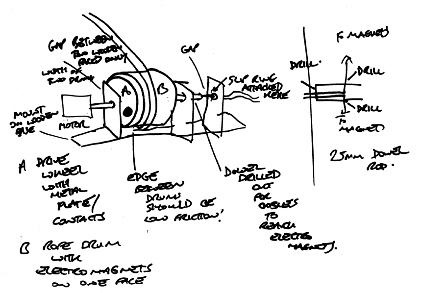
Eventually, I
came up with a way to do it. It was based on the function of
a clutch mechanism in a car, and worked on the idea of being
able to engage and disengage power from a motor with a cable
drum, onto which the rope holding the guillotine blade could
be wound.
How to make possible this connection and disconnection? The
plan was to use my secret weapon for 2017...the electromagnet! |
|
|
 |
|
|
|
|
|
|
|
|
|
|
|
|
|
|
|
|
|
|
|
| |
|
 |
|
|
|
|
|
|
|
|
|
|
|
|
|
|
|
|
|
|
|
|
|
|
|
|
|
|
| |
|
|
|
|
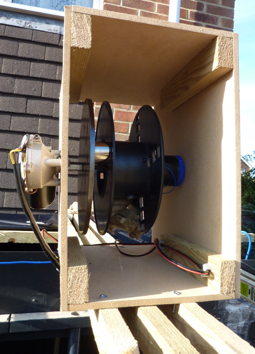
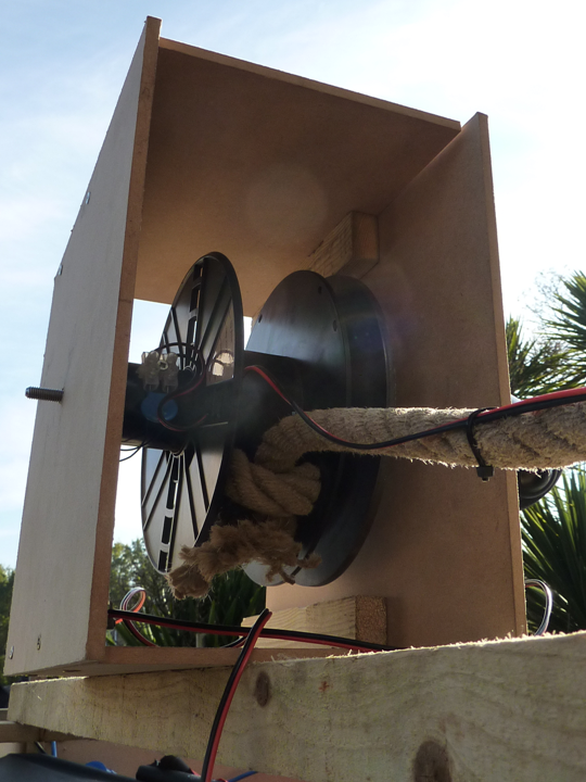
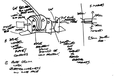
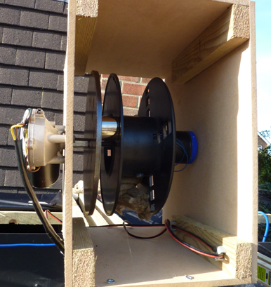
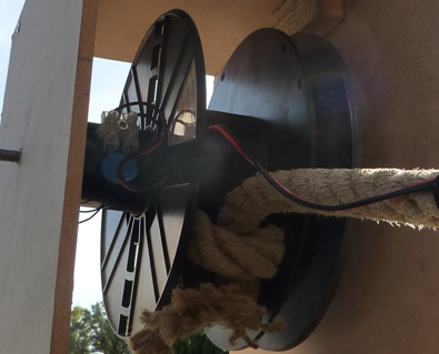
< This is the
assembly that I came up with. A 12V motor was connected to a
long threaded rod. On this rod was a steel disc, fixed such
that it was rotated by the motor. Next was a cable drum with
a length of rope attached. This drum was able to spin freely
on the rod. Mounted on the side of the drum was an
electromagnet. This is the small silver cylinder in the
photo to the left.
When this was powered, the drum would be magnetised to the
steel disc, and would be rotated when the motor was switched
on. This would wind the rope onto the drum, and thus the
weight attached to the rope would be winched upwards. |
|
|
|
|
|
|
|
|
|
|
|
|
|
|
|
|
|
|
|
|
|
|
|
| |
|
|
|
|
 |
|
|
|
|
|
|
|
|
|
|
|
|
|
|
|
|
|
|
|
|
| |
|
When the weight
reached the required height, the motor would be switched
off, but the electromagnet would remain powered. This would
hold the weight in the raised position. When it was time to
drop the weight, the magnet would be switched off.
The drum
would lose its grip on the steel disc, and the weight would
fall downwards, unwinding the rope from the drum.
|
|
|
|
|
|
|
|
|
|
|
|
|
|
|
|
|
|
|
|
|
|
| |
|
 |
|
|
|
|
|
|
|
|
|
|
|
|
|
|
|
|
|
|
|
|
|
|
|
|
| |
|
|
|
Looking at the
other ideas I had planned, I realised that two other scenes
could be animated in the same way.
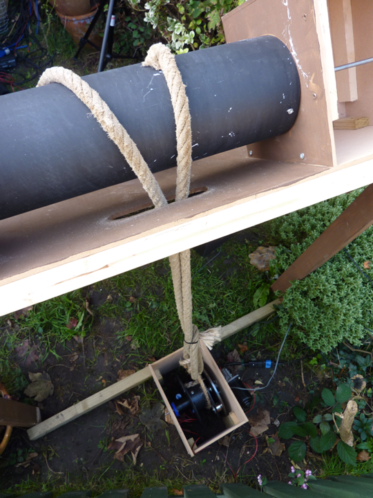
< The figure on the gallows, held in a noose above
trapdoors, could be dropped and winched using the same
method. |
|
|
| |
|
|
|
 |
|
|
|
|
|
|
|
|
|
|
|
|
|
|
|
|
|
|
|
| |
|
The figure on
the torture rack could also be ‘stretched’ using a similar
mechanism, this time operating on a smaller scale – instead
of displacing the moving part by about a metre, this one
would move the figure by only 30cm or so, before releasing.
This all sounded good, but it needed testing. So I got the
bits and stuck it all together. And... it worked! The motor
and magnet seemed quite capable of lifting loads over three
times heavier than what was required!
But the guillotine presented another problem; how would the
electronic system that would eventually be
controlling this prop know when the blade had been winched
up high enough, and stop the motor? |
|
|
|
|
|
|
|
|
|
|
|
|
|
|
|
|
|
|
|
|
|
| |
|
 |
|
|
|
|
|
|
|
|
|
|
|
|
|
|
|
|
|
|
|
|
|
|
|
|
| |
|
|
|
< I attached strong magnets at both edges of the
guillotine blade, in the spaces covered by the wooden frame. In this
frame, at the height that I wanted the blade to stop, and
directly in line with these magnets, two reed switches were
fitted. These are components that can open or close an
electrical circuit when placed in a magnetic field.
When the blade was winched upwards, its magnets would
eventually pass over these reed switches. The controller for
the guillotine would be waiting for this trigger, and would
stop the motor once it was sensed.
In the event of a fault and this not happening, the
controller was programmed to switch the motor off
automatically after six seconds of waiting, to prevent
damage to the prop or motor assembly!
|
|
|
| |
|
|
|
|
|
|
|
|
|
|
|
|
|
|
|
|
|
|
|
|
|
|
|
|
|
|
|
|
|
|
| |
|
Magnetic nastiness,
and how to avoid it |
|
|
|
|
|
|
|
|
|
|
|
|
|
|
|
|
|
|
|
|
|
|
|
|
|
|
|
|
|
|
|
|
|
| |
|
This was a
system that relied on a motor, electromagnetism and gravity
to operate. I hope Messrs Faraday and Newton would have
approved…! Having incorporated some of the scientific
principles of these two great physicists into my own
contraption (not to mention the design principles of a
certain Heath Robinson...) it seems only right to mention an
important point about using electromagnets in an electronic
circuit...
For my early tests, I was simply plugging in and unplugging
two 12V power supplies; one for the motor, one for the
magnet. This was eventually going to be connected to a relay
system and controller, so what about protecting them from
the collapse of the big magnetic field
created by the electromagnet?
|
|
|
|
|
|
|
|
|
|
|
|
|
|
|
|
|
|
|
|
|
|
|
|
|
|
|
|
|
|
|
|
|
|
| |
|
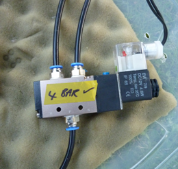
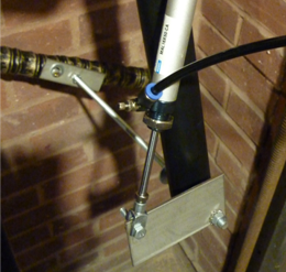
I connected a metal oxide varistor (MOV) in parallel with the
electromagnet. This is the circular, blue component in the
photo
to the right.
This had a rated voltage of about 14V, chosen as it was
slightly higher than the standard 12V operating voltage of
the system. Below 12V, the MOV had a very high resistance.
Thus while the power supply to the magnet was connected at
the standard operating voltage (12V), it had no effect.
It only worked its magic when the power supply was
disconnected. At this point, the back EMF (electromotive
force) created by the
magnetic field collapsing was clamped by the MOV at its
rated voltage; around 14V. This way, it dissipated the
unwanted energy safely, without harm to the control circuits
or relays.
This happened in a fraction of a second; the magnet was
able to completely lose its grip on the steel disc very
quickly, allowing the unwinding of the drum to
begin instantly. |
|
|
 |
|
|
|
|
|
|
|
|
|
|
|
|
|
|
|
|
|
|
|
|
|
|
|
|
|
|
|
|
|
|
|
|
|
| |
|
Initially, I had
struggled to come up with a way of getting power to the
magnet, since it would be mounted on a freely rotating drum,
and I didn’t want its wires to get tangled…a slip ring
assembly, perhaps? I later realised during testing that the
drum would only complete about five rotations before
unwinding the opposite way again…the answer was to simply
fix the wires along the nearest metre of rope such that that
they would be wound and unwound from the drum with it!
Getting these motor assemblies working reliably was
a big step forward in the development of the moving
elements of this year's show. Props in three separate
animated scenes were to use these to provide their key 'drop'
movements. Seeing that this idea had worked spurred me on to build the pneumatic figures and other set
pieces to go with them.
|
|
|
|
|
|
|
|
|
|
|
|
|
|
|
|
|
|
|
|
|
|
|
|
|
|
|
|
|
|
|
|
|
|
| |
|
The brains of the show |
|
|
|
|
|
|
|
|
|
|
|
|
|
|
|
|
|
|
|
|
|
|
|
|
|
|
|
|
|
|
|
|
| |
|
 |
|
|
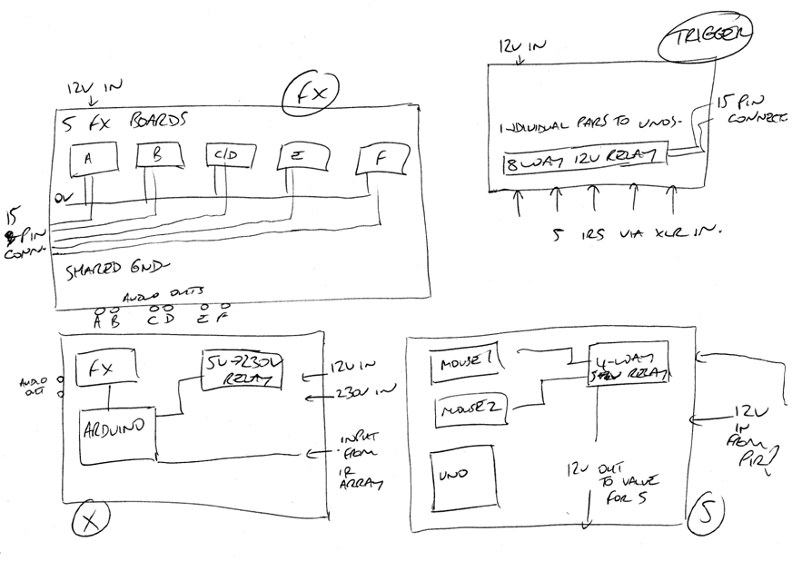
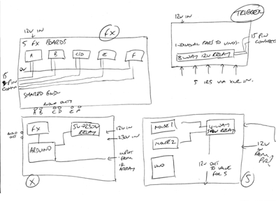
The system in
charge of running the show was made up of seven Arduino Uno
controllers, which ran the animation and effects for the five scenes inside the walkthrough,
and the two moving figures outside.
Each of these
controllers recalled a CD-quality audio file, at random (for
scenes with multiple tracks) from one of seven Adafruit
FX audio boards. There were also about 25 relays, controlled by
the Arduino boards to switch 12V circuits for
air valves and motors, as well as 230V circuits for scene
lighting.
The triggering for each scene controller was done in the
same way as in 2016; infra-red
sensors fixed into the wall at the necessary points. When a
person walked past, they interrupted the IR beam and the
sequence was triggered. |
|
|
|
|
|
|
|
|
|
|
|
|
|
|
|
|
|
|
|
|
|
|
|
|
|
|
|
|
|
|
|
|
| |
|
There were five IR sensors
inside the walkthrough, and a sixth in the porch to trigger
the skeleton on the wall. The seventh figure was to be part
of a charity collection feature, and relied on detecting
coins being dropped through a donation slot (again, via
infra-red sensing) to begin animating.
Inside the house were three computers running VenueMagic DMX
timelines; one for running looped flickering effects for the
green PAR 16 lighting inside the tunnel, and another two for
controlling DMX lighting elements in the first and third
scenes.
The sound system inside the walkthrough used four amplifiers
and nine speakers, with another two speakers and two
single-channel amplifiers for the two moving figures along the
path outside.
|
|
|
|
|
|
|
|
|
|
|
|
|
|
|
|
|
|
|
|
|
|
|
|
|
|
|
|
|
|
|
|
|
|
|
| |
|
The dungeon takes shape |
|
|
|
|
|
|
|
|
|
|
|
|
|
|
|
|
|
|
|
|
|
|
|
|
|
|
|
|
|
|
|
|
|
| |
|
Building the
structure again was good fun - it brought back lots of
memories of the 2016 show. But the job was still as huge as
before, if not bigger! Props such as the guillotine and the
torture rack were so big that they wouldn't have fitted
through the finished walkthrough to be positioned, so they
had to be transported and stored at the back of the garden
before any of the structure was built! |
|
|
|
|
|
|
|
|
|
|
|
|
|
|
|
|
|
|
|
|
|
|
|
|
|
|
|
|
|
|
|
|
|
|
| |
|
 |
|
|
|
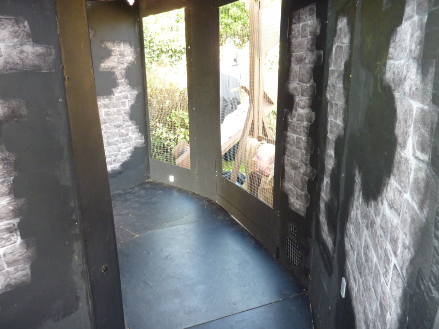
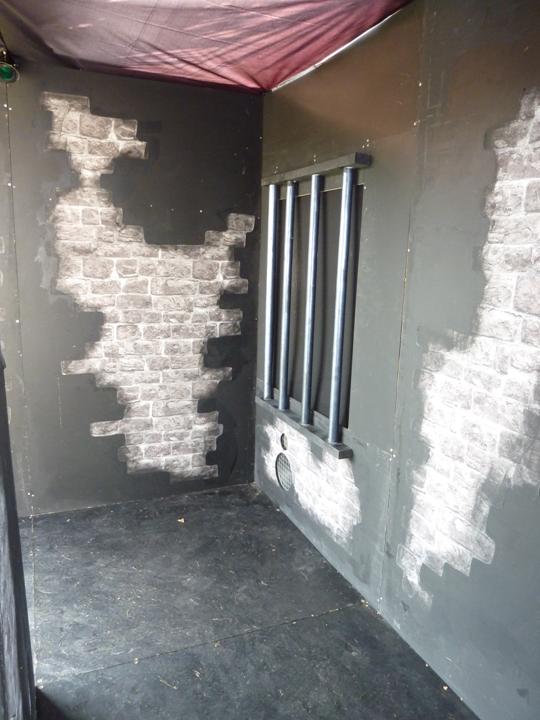
The wall and floor pieces were reassembled to produce the
same walkthrough structure as the previous year. Some of the
scenes required the windows to be a different shape (mainly
to obscure 'workings' that needed to be hidden!) so some
of the wall pieces were re-cut, and some were replaced by
new pieces.
I wanted the inside to feel a bit different to the 2016
show, so I replaced all the red brick vinyl
with a grey, stone effect, to match the dungeon theme.
The walls themselves were also repainted with black emulsion
to freshen them up.
Nylon material was stapled across the tops of the walls to
create a roof and to keep out unwanted light. |
|
|
|
 |
|
|
|
|
|
|
|
|
|
|
|
|
|
|
|
|
|
|
|
|
|
|
|
|
|
|
|
|
|
|
|
|
|
| |
|
 |
|
|
|
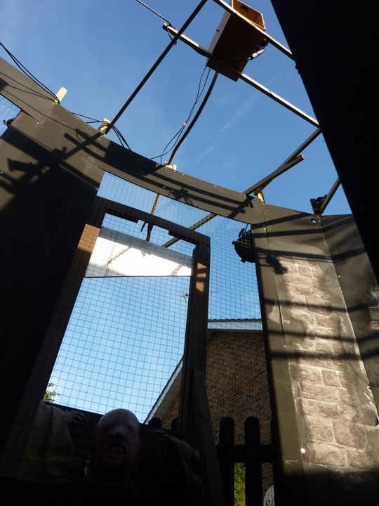
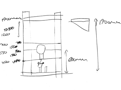
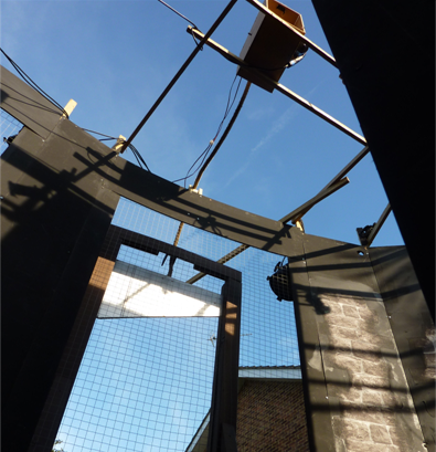
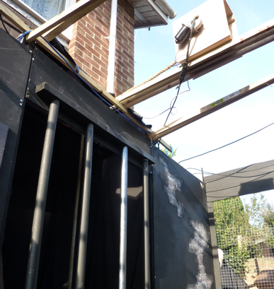
Once the
structure was completed, I began building the scenes. The
challenge this year was making sure that there was enough
space behind each window to fit the props and figures!
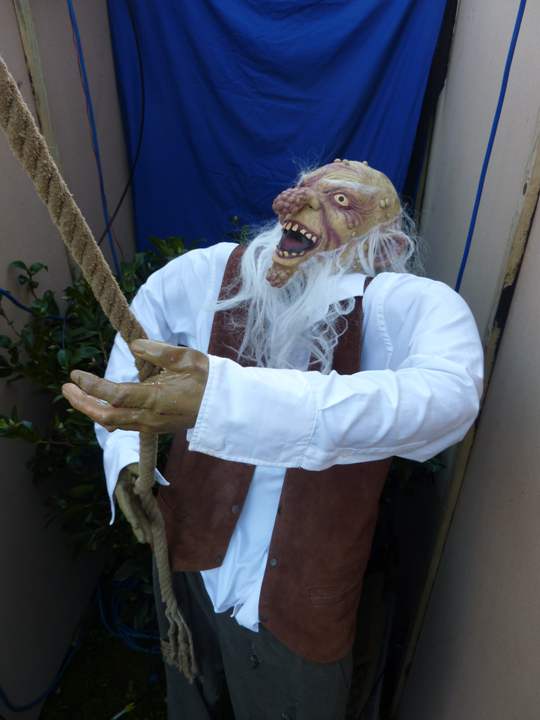
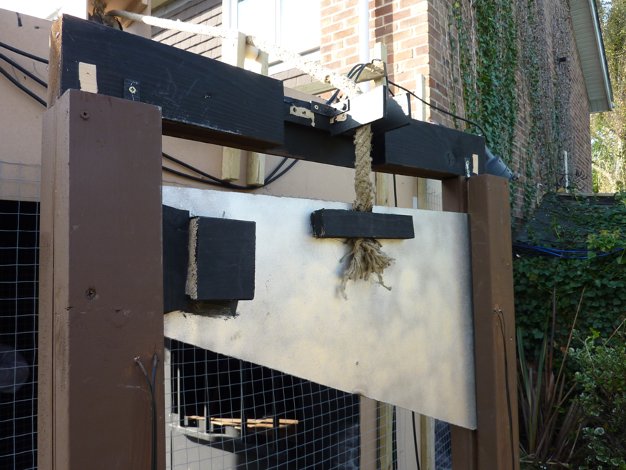
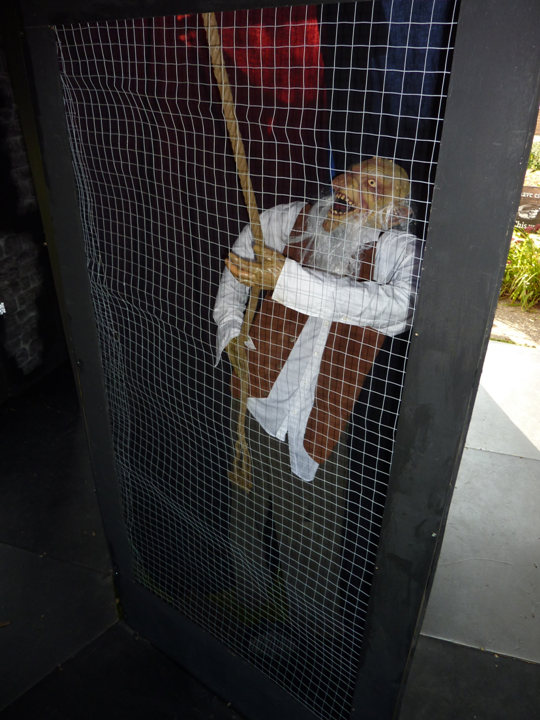
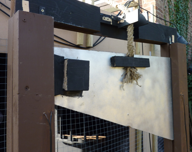
< There was a lot going on in the centre of the tunnel!
Behind this figure with the rope was a curtained-off space
containing the lighting dimmers and most of the air valves.
On the other side of all that was the workings of scene A,
itself covered over by a black drape on the side nearest the
path so it couldn't be seen when exiting.
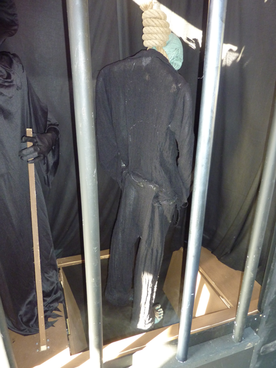
> The gallows scene with the victim in the noose was another
tight fit! Behind the black drapes, there was about a 1cm gap
between the back of the trapdoor floor and the window of the
house behind! |
|
|
|
 |
|
|
|
|
|
|
|
|
|
|
|
|
|
|
|
|
|
|
|
|
|
|
|
|
|
|
|
|
|
|
|
|
|
| |
|
 |
|
|
|
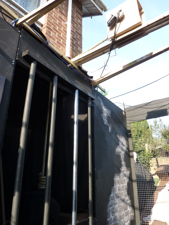
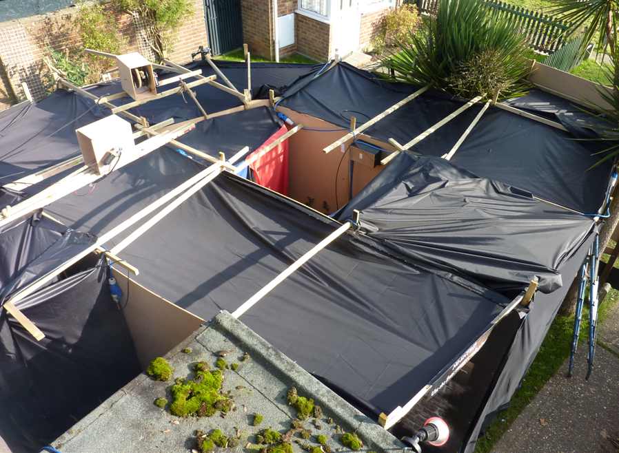
< Attached to
the joists above the roof material, hidden out of sight,
were the two motor boxes for moving the guillotine and the
gallows victim.
The whole walkthrough took about a week to complete,
starting with laying the base cables on October 23rd. From
there followed several long days of assembling and testing
everything. The weather was very kind to me once again, with
lots of sun and dry spells, which made it much easier to
install.
There were some great effects to be unleashed on visitors
this year, and it was exciting for me to see the scenes
fully operating for the first time. By the end of October
30th, everything inside the walkthrough worked correctly -
phew! |
|
|
|
 |
|
|
|
|
|
|
|
|
|
|
|
|
|
|
|
|
|
|
|
|
|
|
|
|
|
|
|
|
|
|
|
|
|
| |
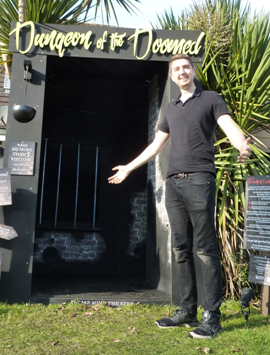
On the morning
of the big day, I added in the signs and the external
lighting for the front of the walkthrough. When the darkness
fell in the evening, it was, at last...time for the dungeon
to open! |
|
|
|
|
|
|
|
|
|
|
|
|
|
|
|
|
|
|
|
|
|
|
|
|
|
|
|
|
|
|
|
|
|
|
| |
|
 |
|
|
|
|
|
|
|
|
|
|
|
|
|
|
|
|
|
|
|
|
|
|
|
|
 |
|
|
|
|
|
|
|
|
|
|
|
|
|
|
|
|
|
|
|
|
|
|
|
|
|
|
|
|
|
|
|
|
|
|
|
|